

AES
(American Energy Services)
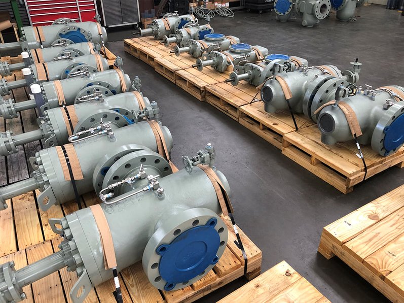

Ball Valves
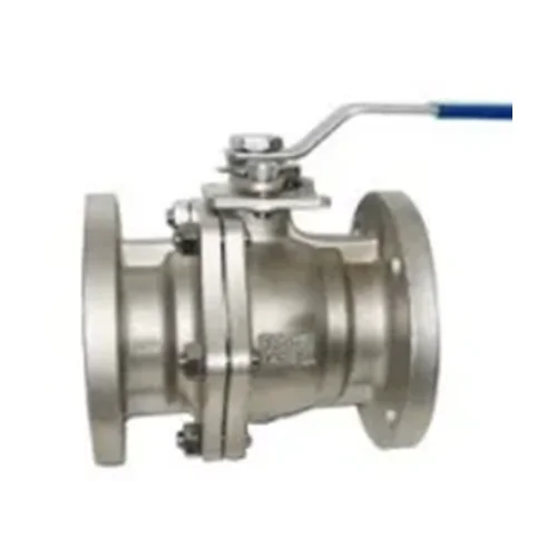
 Ball valve is a form of quarter-turn valve which uses a hollow, perforated and pivoting ball to control flow through it.
Ball valve is a valve with a spherical disc (or ball) that works to control the flow through it.
The ball (sphere) has a hole (known as a port) that when in line or open allows flow to occur.
When the valve is closed the hole is perpendicular to the ends of the valve thus stopping flow.
It is open when the ball's hole is in line with the flow and closed when it is pivoted 90-degrees by the valve handle.
Ball valves are durable, performing well after many cycles, and reliable, closing securely even after long periods of disuse.
These qualities make them an excellent choice for shutoff and control applications, where they are often preferred to gate and globe valves, but they lack their fine control in throttling applications.
Butterfly Valves
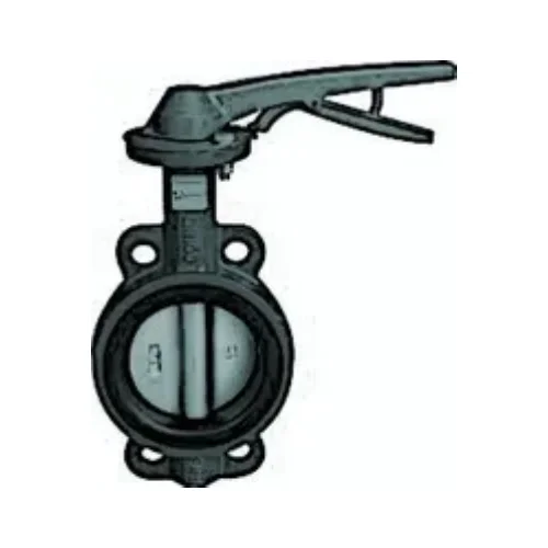
Butterfly valves are used for isolating or regulating flow. They are a quarter turn valve similar to a ball valve except the closing mechanism is a disk instead of a ball.
Butterfly valves are typically lower in cost to other valve types as they are lighter in weight meaning less support is required to have them in line.
The disc of the valve is operated by either a lever, gear or actuator.
When the valve is closed the disc blocks the flow- when open the disk turns to allow flow to pass through; however the disk will always be present within the flow resulting in a pressure drop regardless of valve position.
Butterfly valves can also be open incrementally to throttle flow.
Check Valves
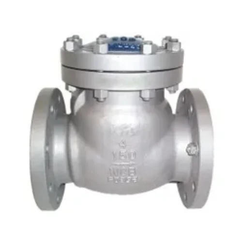
Check valves are two-port valves, meaning they have two openings in the body, one for fluid to enter and the other for fluid to leave.
There are various types of check valves used in a wide variety of applications.
Check valves work under flow pressure automatically without any human intervention or outside controls, most do not have any valve handle or stem.
As the fluid reaches the valve, the gate opens to allow the fluid to move through the valve and then reseats itself once the fluid is completely through. This valve is the ideal choice for preventing backflow.
An important concept in check valves is the cracking pressure which is the minimum upstream pressure at which the valve will operate. Typically the check valve is designed for a specific cracking pressure
Gate Valves
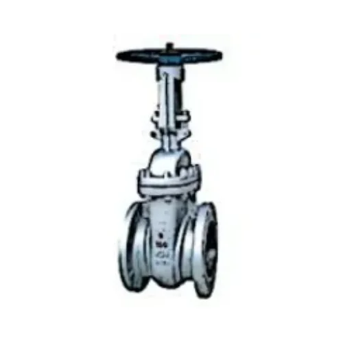
Gate valve operates using a round/rectangular gate (wedge) out of the path of the fluid.
The distinct feature of a gate valve is the sealing surfaces between the gate and seats are planar, so gate valves are often used when a straight-line flow of fluid and minimum restriction is desired.
The gate faces can form a wedge shape or they can be parallel. Typical gate valves should never be used for regulating flow, unless they are specifically designed for that purpose.
On opening the gate valve, the flow path is enlarged in a highly nonlinear manner with respect to percent of opening. This means that the flow rate does not change evenly with stem travel.
Also, a partially open gate disk tends to vibrate from the fluid flow. Most of the flow change occurs near shutoff with a relatively high fluid velocity causing disk and seat wear and eventual leakage if used to regulate flow.
Typical gate valves are designed to be fully opened or closed. When fully open, the typical gate valve has no obstruction in the flow path, resulting in very low friction loss.
Gate valves are ideally suited for petroleum applications because they perform well with viscous fluids.
Globe Valves
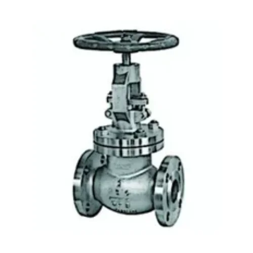
Globe valve is a linear valve used to start, stop and regulate flow. The globe valve disk can be completely or partially removed from the flow or it can completely close the flow.
Globe valves are used for applications requiring throttling and frequent operation. For example, globe valves or valves with a similar mechanism, may be used as sampling valves, which are normally shut except when liquid samples are being taken.
Since the baffle restricts flow, globe valves are not recommended where full, unobstructed flow is required.
Used primarily for regulating flow in a pipeline, globe valves are the top choice for oil & gas, petrochemical and hydropower industries because of their smooth operation and tested reliability.
Globe valves have a spherical body that is internally separated by a baffle. The opening in the baffle forms the seat in which the disk (plug) is lowered into to close or shut the valve to stop the flow of fluids.
The proportional relationship between the disk and the seat enables precision flow regulation.
All globe valves provide leak-proof operation, resistance to harsh chemicals and environments, and extended life under frequent operation.
Plug Valves
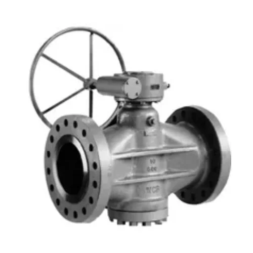
Plug valves are valves with cylindrical or conically-tapered plugs which can be rotated inside the valve body to control flow through the valve.
The plugs in plug valves have one or more hollow passageways going sideways through the plug, so that fluid can flow through the plug when the valve is open.
Plug valves are simple, often economical and ideally suited for viscous liquids.
When the plug is conically-tapered, the stem/handle is typically attached to the larger diameter end of the plug.
Plug valves usually do not have bonnets but often have the end of the plug with the handle exposed or mostly exposed to the outside.
In cases like that, there is usually not much of a stem. The stem and handle often come in one piece, often a simple, approximately L-shaped handle attached to the end of the plug.
The other end of the plug is often exposed to the outside of the valve too, but with a mechanism which retains the plug in the body.
Control Valves
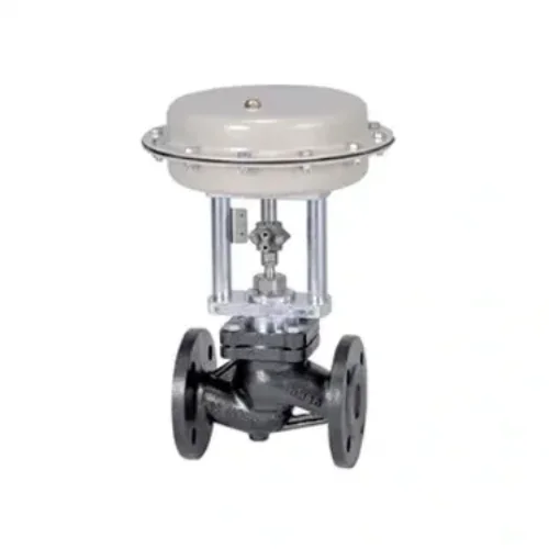
A control valve regulates the rate of fluid flow as the position of the valve plug or disk is changed by an actuator.
Control valves are used to maintain a process variable as close as possible to the desired set point. Controller set points are typically flow rate, pressure, and temperature.
Control valves ensure pressure management in the supply network. Automatic control valves are used to obtain efficient pressure and flow management resulting in: Reduced water loss through leakages. Reduced risk of water hammer and pipe bursts
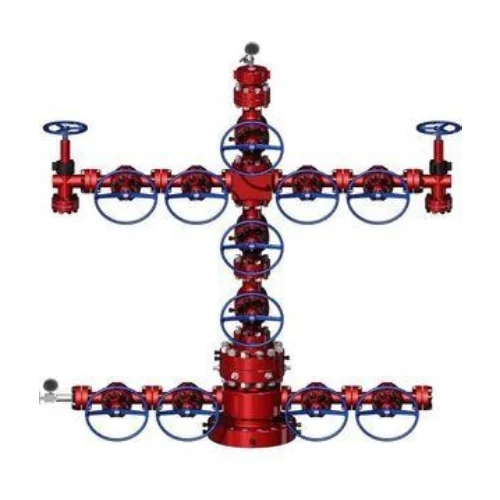
Wellhead & X-Mas Tree
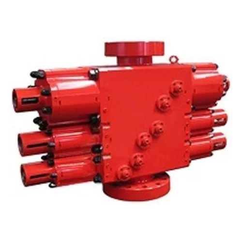
A wellhead is the component at the surface of an oil or gas well that provides the structural and pressure-containing interface for the drilling and production equipment.
The primary purpose of a wellhead is to provide the suspension point and pressure seals for the casing strings that run from the bottom of the hole sections to the surface pressure control equipment.
Wellheads are typically welded onto the first string of casing, which has been cemented in place during drilling operations, to form an integral structure of the well. In exploration wells that are later abandoned, the wellhead may be recovered for refurbishment and re-use.
Offshore, where a wellhead is located on the production platform it is called a surface wellhead, and if located beneath the water then it is referred to as a subsea wellhead or mudline wellhead.
More Information
